Heliodon
- Ardavan

- Jun 3, 2020
- 6 min read
Updated: Aug 27, 2020
Heliodons are a physical simulation apparatus to help architects study the behavior of a building shape against sunlight over the span of a year.
A basic heliodon consists of a light source that produces-almost-parallel light rays a horizontal plane to contain the model of building and a mechanical system to move one of the two to mimic the sun path over an arbitrary period of time.
In this research, we are aiming to design and prototype a heliodon using an articulated industrial robotic arm with six-degree-of-freedom. In the process of designing this system, we should make three major design decisions:
Scale
Scale determines the size of the system, which eventually determines the Size of models we can conduct a study on.
The robotic system
The robotic system determines which robotic arm and which external tools we can use. This decision is directly associated with the size as well as mobility and complexity of the system.
Using an ABB 120 robot let us move the robot out of the robotic lab and into the studios. But it requires us to design a custom-made rotating table to address the reachability and configuration issues of this robot.
Using an ABB 4400 with an integrated rotating table is another solution that makes it easier to implement the rotating mechanism, but it limits the test into the lab environment.
Using an ABB 6640 on a linear track is the ultimate solution that lets us move the robot to a larger zone and study larger models.

Light source:
Rays: The light source should emit parallel rays to accurately represent sun rays. However, it is technically impossible and we need to compensate for this problem by using lenses and reflectors. The two possible options are:


Color: The color temperature of sunlight varies slightly during the day (6000-6500K) but changes drastically in golden hours (4500). We can achieve these temperatures by combining two or more light sources (3-5 Watt LEDs) and interpolate between the values.

Implementations
We implemented the workflow in Grasshopper's visual programming environment for Rhino. The pipeline let us calculate the sun path for a specific city and generate robotic toolpath to follow the sun path over 365 days of the year from 8:00 to 17:00 on one-hour intervals.
Sun path:
To calculate the sun path, we first tested off-the-shelf tools for Rhino/Grasshopper such as DIVA and Honeybee-Ladybug. However, the dependencies and installation limitations would add extra challenges, thus we decided to implement the sun tracking using CPython plug-in for Grasshopper. This plug-in lets us use Python 3.x and its packages directly in the Grasshopper environment and taps on the Python version that is already installed on the system. We used pyphem_sunpath and astral packages to calculate sun ray’s directions at each timestamp. These directions are processed to produce light source poses with respect to the model’s position in front of the robot.
from pyephem_sunpath.sunpath import sunpos
from astral.geocoder import database, lookup
from datetime import timedelta, date, datetime
import numpy as np

# city data
cityData = lookup(city, database())
lat = cityData.latitude
lon = cityData.longitude
tz = -5

# fixed values
month_len = [31,28,31,30,31,30,31,31,30,31,30,31]
month_data = []
day_start = 8
day_end = 17

for m in  range(12):
   this_month= []
   for d in range (1, month_len[m]+1):
      for h in range (day_start,day_end):
            tmp_time = datetime(2020, m+1, d, h)
            data_point = sun
            this_month.append(data_point)
            this_month= np.array(this_month)
            this_month= this_month.reshape(month_len[m],day_end-day_start)
            print (this_month.shape)
            month_data.append(this_month)
Robotic Path Planning
We utilize HAL plug-in for Grasshopper to convert the light source poses into robot target points and toolpaths. HAL also calculates the Robot’s joint configurations as well as rotating table angles for each timestamp which helps us to visualize the process and control the process and converts them into the RAPID language which runs on ABB robots.
//As we do not possess a rotating table for the ABB 120 robot, we develop a custom-made rotating table using an Arduino control board as well as a high-torque step motor. The Arduino board also controls the light source simultaneously. The servo-motor has 1024 steps over 300 degrees of rotation, which provides us with ~0.29-degree accuracy. //
We will encode the color and the rotating values as a 16-bit binary data and send it over the digital outputs of the controller and collect them on the Arduino board. Then the board will command the servo-motor over its serial communication terminal and the LED’s using its PWM digital output pins.
Using the ABB 4400 and its integrated rotating table gives us far more accurate results as well as simplified Workflow as it doesn’t require the Arduino integration for the servo.
Modes of Analysis
Once the Grasshopper definition generates the target points, the user can load them on the robot controller using RobotStudio interface.
On the teaching pendant, the user can have four different forms of usage for the system:
1- Critical days' analysis
In this mode, the robot only simulates four critical days of a year: March 21st, June, 21st, Sep. 21st, and Dec 21st, all at noon. Having the sunlight at these four points gives us a better understanding of the overall status of the building. The robot will stop at the end of each day and asks for permission to proceed.
2- One-day analysis
In this mode, the user selects a date by month and day and the robot will simulate the sun path from 09:00 to 17:00.
3- Fix hour across a year
In this mode, the user selects a specific time of the day and the robot will move over that time over the span of the year.
4- Whole year simulation
The robot will simulate the sun path for 365 days of a year from 09:00 to 17:00.

Lighting
To simulate the correct intensity and color of sunlight, we opted to use Gantom controllable light fixtures. The benefits of using these light sources a main These lights are two-folded:
The reflectors in the light fixture prived a narrow spot to roughly simulate the parallel rays of sunlight.
The DMX interface helped us to directly control the color temperature in real-time using an Arduino board and MAX13487 chip.

We used the DMXSimple library to send commands over the DMX protocol.
For the seven-channel light, we just need to send the channel number (1-7) with a value between 0 and 255:
ch1 is for intensity
ch2 red
ch3 green
ch4 blue
ch5 amber
ch6 warm white
ch7 lime?
ch8 ultraviolet
The simpler spotlight only emits cool white and warm light, thus it only has two channels:
ch1 cool white
ch2 warm light
Tests on the robot
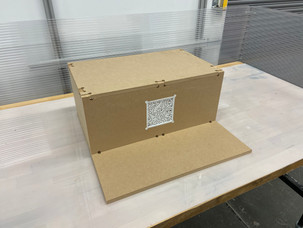
We tested the system using a interchangable frame to swap varios window shaders. This system let us compare various design alternatives using 3d printed patterns quickly.


A simple code to control the light color in Arduino language looks like this:
#include <DmxSimple.h>
/* For the Seven Color DMX Spotlight:
 *  Ch1: Intensity of light
 *  Ch2: Red
 *  Ch3: Green
 *  Ch4: Blue
 *  Ch5: Orange?
 *  Ch6: Cool white
 *  Ch7: Warm white
 *  Ch8: UV?
 */


const int b_pin = 2;
const int led_pin = 13;
int buttonState;


void setup() {
  /* for this project, we use pin 3 to communicate with the
  ** DMX baord it can be mapped into any pmw pin.*/
  DmxSimple.usePin(3);


  /* We just need 2 channels for DMX Spot and 7 channels
  ** for Color DMX Spotlight.*/
  DmxSimple.maxChannel(4);


  /* the button test
      Just a simple button to test the code.
  */
  pinMode(led_pin, OUTPUT);
  pinMode(b_pin, INPUT);

  DmxSimple.write(1, 50);
  DmxSimple.write(2, 200);
  delay(1000);
}


void loop() {
  check_button();
}

void check_button() {
  buttonState = digitalRead(b_pin);
  if (buttonState == HIGH) {
    digitalWrite(led_pin, HIGH);
    DmxSimple.write(1, 255);
    DmxSimple.write(2, 0);
    DmxSimple.write(6, 200);
    DmxSimple.write(7, 0);
    delay(100);
  }

  if ( buttonState == LOW)
  {
    digitalWrite(led_pin, LOW);
    DmxSimple.write(1, 255);
    DmxSimple.write(2, 0);
    DmxSimple.write(6, 0);
    DmxSimple.write(7, 200);
    delay(100);
  }
}

void fader() {
  int brightness;
  for (brightness = 0; brightness <= 255; brightness++) {
    DmxSimple.write(1, brightness);
    DmxSimple.write(2, 255 - brightness);
    delay(10);
  }
}
In the next step, the light values will be communicated from the Robot's DO signals and will be collected using digital pins on the Arduino board.
/*
  Control Gantom Lights using RAPID code and Arduino board.
  By: Ardavan Bidgoli | Robotics Fellow @ CMU, SoA

  Collects the signals from 4-6 Digital Outputs from an ABB controller
  Signals from ABB are in 24v, it will fry Arduino for sure, thus signals are passing through a
  Optocoupler Isolation Board to isolate the board from the high voltage.
  Link to this board: https://www.amazon.com/gp/product/B06XKSFGXX/ref=ppx_yo_dt_b_asin_title_o00_s00?ie=UTF8&psc=1
  The signals to the Gantom fixture are passed through a RS485 to TTL board.
  Link to this board: https://www.amazon.com/gp/product/B07B667STP/ref=ppx_od_dt_b_asin_title_s00?ie=UTF8&psc=1

  Operations modes:
  0- Checks the button input
  1- Listens to the ports from the robot
  2- Listens to the serial input
*/


#include <DmxSimple.h>
// global variables
const int b_pin = 2;
const int led_pin = 13;

int buttonState;
int channel_size = 2;
int operation_mode = 2;
int serial_input;


//////////////////////////////////////////////////////////
//////////////////// Main Setup //////////////////////////
//////////////////////////////////////////////////////////
void setup() {
  /*
    for this project, we use pin 3 to communicate with the
    DMX baord it can be mapped into any pmw pin.
  */
 DmxSimple.usePin(3);

  /*
    We just need 2 channels for DMX Spot and 7 channels
    for Color DMX Spotlight.
  */
 DmxSimple.maxChannel(channel_size);

  /* The button test:
    Just a simple button to test the code.
    led_pin to monitor the state of button.
  */
 pinMode(led_pin, OUTPUT);
 pinMode(b_pin, INPUT);

  // for the sake of communication
 Serial.begin(9600);
}


//////////////////////////////////////////////////////////
////////////////////// Demo (Mode 0) /////////////////////
//////////////////////////////////////////////////////////
void fader() {
 int brightness;
 digitalWrite(led_pin, LOW);
 for (brightness = 0; brightness <= 255; brightness++) {
    /* Update DMX channel 1 to new brightness */
 DmxSimple.write(1, brightness);
    /* Update DMX channel 1 to new brightness */
 DmxSimple.write(2, 255 - brightness);
    /* Small delay to slow down the ramping */
 delay(10);
  }
}

void fixed_temp() {
 digitalWrite(led_pin, HIGH);
  /* Update DMX channel 1 to new brightness */
 DmxSimple.write(1, 200);
 DmxSimple.write(2, 0);
}

void check_button() {
 buttonState = digitalRead(b_pin);
 if (buttonState == HIGH) {
 fader();
  }
 if ( buttonState == LOW)
  {
 fixed_temp();
  }
}


//////////////////////////////////////////////////////////
///////////// READING FROM THE ROBOT DOs (Mode 1) ////////
//////////////////////////////////////////////////////////
int read_data_from_octocouple() {
  // this is the placeholder
 int variable_read [6] = {0, 0, 0, 0, 0, 0};
  // reading all pins
 variable_read [0] = digitalRead(A0);
 variable_read [1] = digitalRead(A1);
 variable_read [2] = digitalRead(A2);
 variable_read [3] = digitalRead(A3);
 variable_read [4] = digitalRead(A4);
 variable_read [5] = digitalRead(A5);

  // report and summing the digits
 int sum_val = 0;
 for (int i = 5 ; i > -1 ; i--) {
 Serial.print(variable_read[i]);
 int tmp_val_now = (powint(2, i) * variable_read[i]);
 sum_val += tmp_val_now;
  }

  // final report
 Serial.println();
 Serial.println(sum_val);
 Serial.println("---------");
 return sum_val;
}

// because Arduino pow function is stupid!
int powint(int x, int y)
{
 if (y == 0) {
 return (1);
  }
 else
  {
 return (powint(x, y - 1) * x);
  }
}

void check_input_from_robot(int color_val = 100) {
 if (color_val == 100)
  {
 int color_val = read_data_from_octocouple();
  }

  // define the temp of light
  // we have eight values for the temp and we interpolate between them
  // the real value should be between 6000 to 6500 K
  // we apply a 100 K step to go from 6100 to 6500 and back
  // NEXT STEP: then we send a signal back?
 switch (color_val)
  {
 case 0:
      // if the value is too low, then we turn off the LED
      // Basically if all the DO's are zero, then no light!
 set_color_temp(0, 0);
 break;
 case 1:
      //6200
 set_color_temp(225, 30);
 break;
 case 2:
      //6300
 set_color_temp(235, 20);
 break;
 case 3:
      //4200
 set_color_temp(245, 10);
 break;
 case 4:
      //6500
 set_color_temp(255, 0);
 break;
 case 5:
      //6400
 set_color_temp(245, 10);
 break;
 case 6:
      //6300
 set_color_temp(235, 20);
 break;
 case 7:
      //6200
 set_color_temp(225, 30);
 break;
 case 8:
      //6100
 set_color_temp(215, 40);
 break;
 default:
 set_color_temp(0, 0);
  }

}


//////////////////////////////////////////////////////////
////////////// READING FROM SERIAL (Mode 2) //////////////
//////////////////////////////////////////////////////////
void check_serial() {
 int hour = Serial.parseInt();
 if (hour > 0) {
 Serial.print("Setting the value of light to: ");
 Serial.print( hour * 10);
 Serial.print(", ");
 Serial.println(255 - hour * 10);
 set_color_temp (hour * 10,255 - hour * 10);
 delay(1000);
  }
}

//////////////////////////////////////////////////////////
///////////////////// Set Colors /////////////////////////
//////////////////////////////////////////////////////////
void set_color_temp(int ch1, int ch2) {
  // set the coor on the two main channel
 DmxSimple.write(1, ch1);
 DmxSimple.write(2, ch2);
}

//////////////////////////////////////////////////////////
////////////////////// MAIN LOOP /////////////////////////
//////////////////////////////////////////////////////////
void loop() {
 switch (operation_mode)
  {
 case 0:
 check_button();
 break;
 case 1:
 check_input_from_robot();
 break;
 case 2:
 check_serial();
 break;
 default:
 Serial.println("Operation mode is not valid.");
 break;
  }
}
To do: find the exact combination of brightness on both LEDs to come up with accurate color temps.
Comments